Difference between revisions of "Davac5"
(→Connecting to the radio) |
|||
| Line 64: | Line 64: | ||
==Connecting to the radio== | ==Connecting to the radio== | ||
| − | * '''MOD''' - | + | * '''MOD''' - Modulation output to the microphone input of radio |
* '''PTT''' - Push to talk output to switch Radio to the transmit (active low) | * '''PTT''' - Push to talk output to switch Radio to the transmit (active low) | ||
* '''GND''' - One ground (ground plane on the bottom layer) | * '''GND''' - One ground (ground plane on the bottom layer) | ||
| + | |||
| + | * '''MIC''' - Modulation input from headset | ||
| + | * '''BIAS''' - Microphone supply (from soundcard, not from radio) | ||
| + | |||
| + | * '''CW''' - CW output to key to the radio | ||
| + | * '''RES''' - Recording input to record band traffic (RES is a typo, should be REC) | ||
| + | |||
| + | ==LEDs== | ||
| + | * '''PWR lights up''' - Device is powered from USB | ||
| + | * '''PWR blinks''' - Soundcard is playing or recording | ||
| + | * '''PTT''' - Push to talk is active (SSB and also CW) | ||
| + | * '''CW''' - CW in the rhytm of Morse code | ||
| + | * '''MIC''' - The SSR connects '''MIC''' to the '''MOD''' (off/disconnected if CQ is active) | ||
| + | |||
| + | ==Trimmers== | ||
| + | * '''CQ''' - Modulation level to the Transceiver | ||
| + | * '''REC''' - Record level attenuator | ||
Revision as of 23:26, 14 October 2023
Davac 5 is new design of voice/SSB keyer for Tucnak. Although version 5 may appear to be a successor to version 4, is not true. It brings some advantages but also lacks some features.
To choose the version that best suits your requirements, please look at the table:
| Davac 5 | Davac 4 | |
|---|---|---|
| Size | small | bigger |
| Drivers required | No | Yes |
| Isolated | No, use the USB isolator | Yes |
| Band output | No | Yes |
| USB | Micro-B | A |
| Soundcard | Is the soundcard itself | Uses PC soundcard |
| Audio cables | Shorter | Longer |
| Modulation relay | Solid SPST | Mechanical SPDT |
| Separated grounds | No | Yes |
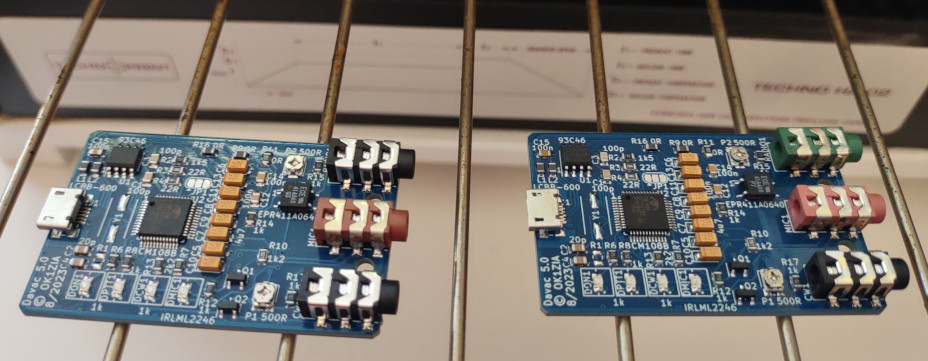
Photos
Features
- Simple assembly
- All parts are SMD
- Designed for SMD reflow
- 3.5 jacks
- 3D printed box
- SMD LEDs + light guides on the top side
- power supply from USB
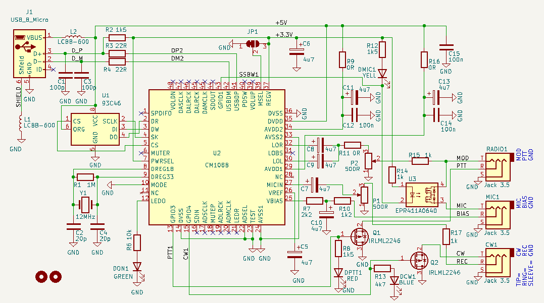
Circuit diagram
Connecting to the radio
- MOD - Modulation output to the microphone input of radio
- PTT - Push to talk output to switch Radio to the transmit (active low)
- GND - One ground (ground plane on the bottom layer)
- MIC - Modulation input from headset
- BIAS - Microphone supply (from soundcard, not from radio)
- CW - CW output to key to the radio
- RES - Recording input to record band traffic (RES is a typo, should be REC)
LEDs
- PWR lights up - Device is powered from USB
- PWR blinks - Soundcard is playing or recording
- PTT - Push to talk is active (SSB and also CW)
- CW - CW in the rhytm of Morse code
- MIC - The SSR connects MIC to the MOD (off/disconnected if CQ is active)
Trimmers
- CQ - Modulation level to the Transceiver
- REC - Record level attenuator


